Refine Your Search

Topic

Author

Affiliation

Search Results

Technical Paper

2.5 D LED: A Cost Efficient Solution for 3 D Signaling Lamps

2007-04-16
2007-01-1231
After the first appearance of LED rear lamps, which employed mainly two-dimensional arrays of LEDs, the request of stylists and OEMs to have three-dimensional LED alignment has increased strongly. Development of more powerful LEDs and new packaging and assembly technologies now allows for a three-dimensional assembly of the LEDs, giving an impression of depth and enabling the LEDs to follow even extreme curvatures. This gives great customer satisfaction in terms of styling, but the disadvantage is that the cost for the three-dimensional LED alignment increases significantly. To counteract this development, we have developed a light guide technology approach (so-called 2.5 D) to combine a cost efficient LED assembly process with the flexibility of a 3 D arrangement of the light sources. Thus, we can use standard planar FR4 (Flame Resistant 4) LED printed circuit boards with arbitrary LEDs and do not depend on a certain assembly technology.
Technical Paper

20 Years of UNSW Australia's Sunswift Solar Car Team: A New Moment in the Sun, but Where to Next?

2015-03-10
2015-01-0073
The Sunswift Solar Car project has been running at UNSW Australia in Sydney for 20 years as of 2015. It is an entirely student-run endeavour which revolves around the design and development of a solar/electric vehicle nominally designed to compete in the World Solar Challenge rally from Darwin to Adelaide every 2 years. The student cohort is drawn from a range of schools, disciplines and backgrounds, and the team has been increasingly successful and high-profile particularly in its second decade. The excellent level of hands-on training that the project provides to students is not rewarded with academic credit yet many of the alumni credit the project with launching their careers and ambitions. The team's world record-breaking latest vehicle, eVe, is the fifth constructed and presents a radical departure from previous cars in that it carries a passenger in a conventional layout and is based around a road-going sports car.
Technical Paper

2002 Joint EPA/SAE-ESSC Workshop Environmental Systems Decision Making

2003-03-03
2003-01-0549
This is a report of a workshop held in mid-August of 2002 at Northwestern University, Evanston, Illinois, to explore what it takes to make a decision regarding environmental systems in the US. The participants in the workshop represented federal government, industry, non-governmental organizations and academia. During the two and a half day workshop, discussions were held on the policy drivers, the strategies and tactics (through a SWOT analysis), the decisions the automotive industry is facing today and the tools available to support decision making.
Technical Paper

2005 Ford GT - Melding the Past and the Future

2004-03-08
2004-01-1251
The 2005 Ford GT high performance sports car was designed and built in keeping with the heritage of the 1960's LeMans winning GT40 while maintaining the image of the 2002 GT40 concept vehicle. This paper reviews the technical challenges in designing and building a super car in 12 months while meeting customer expectations in performance, styling, quality and regulatory requirements. A team of dedicated and performance inspired engineers and technical specialists from Ford Motor Company Special Vehicle Teams, Research and Advanced Engineering, Mayflower Vehicle Systems, Roush Industries, Lear, and Saleen Special Vehicles was assembled and tasked with designing the production 2005 vehicle in record time.
Technical Paper

2005 Ford GT Magnesium Instrument Panel Cross Car Beam

2005-04-11
2005-01-0341
Ford GT 2005 vehicle was designed for performance, timing, cost, and styling to preserve Ford GT40 vintage look. In this vehicle program, many advanced manufacturing processes and light materials were deployed including aluminum and magnesium. This paper briefly explains one unique design concept for a Ford GT instrument panel comprised of a structural magnesium cross-car beam and other components, i.e. radio box and console top, which is believed to be the industry's first structural I/P from vehicle crash load and path perspectives. The magnesium I/P design criteria include magnesium casting properties, cost, corrosion protection, crashworthiness assessments, noise vibration harshness performance, and durability. Magnesium die casting requirements include high pressure die cast process with low casting porosity and sound quality, casting dimensional stability, corrosion protection and coating strategy, joining and assembly constraints.
Technical Paper

2006 Chevrolet Corvette Z06 Aluminum Spaceframe

2005-04-11
2005-01-0465
This paper describes the engineering, manufacturing and integration necessary to produce the Corvette's first ever all-aluminum spaceframe (see Figure 1). The engineering and manufacturing of the spaceframe was a joint venture between General Motors and suppliers ALCOA (Aluminum Company of America) and Dana Corporation. ALCOA led the initial design of the spaceframe; Dana Corp led the manufacturing; General Motors' Engineering and Manufacturing groups led the integration of the assembly. The aluminum spaceframe design is modeled after the baseline steel structure of the Corvette coupe. The aluminum spaceframe reduces 140 lbs from the steel baseline and enters the plant at 285 lbs. This frame allows the 2006 Corvette Z06 to enter the market at a 3100 lbs curb weight. Aluminum casting, extruding, stamping, hydroforming, laser welding, Metal Inert Gas (MIG) welding, Self Pierce Riveting (SPR), and full spaceframe machining make up the main technologies used to produce this spaceframe.
Technical Paper

2006 Chevrolet Corvette Z06 Aluminum Spaceframe Design and Engineering Technology

2005-04-11
2005-01-0466
The General Motors (GM) Corvette design team was challenged with providing a C6 Z06 vehicle spaceframe that maintained the structural performance of its C5 predecessor while reducing mass by at least 56 kg. An additional requirement inherent to the project was that the design must be integrated into the C6 assembly processes with minimal disruption, i.e. seamless integration. In response to this challenge, a collaborative team was formed, consisting of design engineers from General Motors, Alcoa and Dana Corporation. The result of this collaborative effort is an aluminum Z06 spaceframe that satisfies the high performance expectations of the vehicle while reducing the mass by approximately 62 kg. The frame consists of aluminum extrusions, castings and sheets joined by MIG welding, laser welding and self-piercing rivets. The extrusions are 6XXX series alloys, the castings are permanent mold A356 while the sheet panels are formed from the 5XXX series of alloys.
Technical Paper

2006 Chevrolet Corvette Z06 Aluminum Spaceframe Manufacturing Technology

2005-01-11
2005-01-0470
In October 1999, General Motors contracted Dana Corporation to manufacture an all-aluminum spaceframe for the 2006 Chevrolet Corvette Z06. Corvette introduced its first ever all-aluminum frame (see Figure 1) to the world at the 2005 North American International Auto Show (NAIAS) in Detroit, Michigan. The creation of this spaceframe resulted in a significant mass reduction and was a key enabler for the program to achieve the vehicle level performance results required for a Z06 in an ever-growing market. Dana Corporation leveraged ALCOA's (Aluminum Company of America) proven design capabilities while incorporating new MIG welding, laser welding, Self-Pierce Riveting (SPR), and full spaceframe machining to join General Motors (GM) Metal Fabrication Division's (MFD) hydroformed rails to produce the Corvette Z06's yearly requirement of 7000 units. This paper describes the technologies utilized throughout the assembly line and their effect on the end product.
Technical Paper

2006 Corvette Z06 Carbon Fiber Fender- Engineering, Design, and Material Selection Considerations

2005-04-11
2005-01-0468
General Motor's Corvette product engineering was given the challenge to find mass reduction opportunities on the painted body panels of the C6 Z06 through the utilization of carbon fiber reinforced composites (CFRC). The successful implementation of a carbon fiber hood on the 2004 C5 Commemorative Edition Z06 Corvette was the springboard for Corvette Team's appetite for a more extensive application of CFRC on the C6 Z06 model. Fenders were identified as the best application for the technology given their location on the front of the vehicle and the amount of mass saved. The C6 Z06 CFRC fenders provide 6kg reduction of vehicle mass as compared to the smaller RRIM fenders used on the Coupe and Convertible models.
Technical Paper

2006 Corvette Z06 Carbon Fiber Structural Composite Panels- Design, Manufacturing and Material Development Considerations

2005-04-11
2005-01-0469
The General Motors Corvette Product Engineering Team is in a continual search for mass-reduction technologies which provide performance improvements that are affordable and add value for their customers. The structural composite panels of the C6 Z06 provided a unique opportunity to extend the use of carbon fiber reinforced materials to reduce mass and enhance performance. The entire vehicle set of composite panels was reviewed as candidates for material substitution, with the selection criteria based on the cost per kg of mass saved, tooling cost required, and the location of the mass to be saved. Priority was extended to mass savings at the front of the vehicle. After a carefully balanced selection process, two components, both requiring redesign because of the Z06’s wider stance, met the criteria: the Front Wheelhouse Outer Panel and Floor Panels. The current Floor Panels, first used on the C5, are large and are a balsawood-cored glass fiber reinforced composite design.
Book

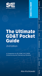
2009 Ultimate GD&T Pocket Guide 2nd Ed

2017-03-27
The Ultimate GD&T Pocket Guide explains the most common rules, symbols, and concepts used in geometric dimensioning and tolerancing. ...This one-of-a-kind reference guide includes over 100 detailed drawings to illustrate concepts, more than 40 charts for quick reference, explanations of each GD&T symbol and modifier and much more...Written by standards expert Alex Krulikowski, this valuable on-the-job reference clarifies how to interpret standard-compliant technical drawings that use ASME Y14.5-2009.
Book

2016 Mobility Engineering Professionals Salary Survey

2016-07-14
EXCLUSIVE MEMBER BENEFIT: 2016 MOBILITY ENGINEERING PROFESSIONAL SALARY SURVEY AND CALCULATOR Gain better insight into compensation practices: this salary survey is the only study its kind to explore levels and changes in compensation and employment for engineers and technical employees in the automotive, aerospace, and commercial vehicle industries. It benchmarks compensation levels based by geography, education, industry sector, experience, and managerial and budgetary responsibility. The full report is available to SAE International members by signing into your My SAE account and downloading it into your My Library area. Members also have full access to the updated online interactive salary calculator by visiting SAE’s website. Become a member of SAE International to access this exclusive benefit for free, or purchase it today. YOU BELONG HERE. Membership helps you succeed both personally and professionally. Join us today.
Technical Paper

250 °C SiC Power Module Package Design

2008-11-11
2008-01-2892
In order to take full advantage of SiC, a high temperature package for power module using SiC devices was designed, developed, fabricated and tested. The details of the material selection and fabrication process are described. High temperature reliability test and power test shows that the package presented in this paper can perform well at the high junction temperature.
Technical Paper

2D Finite Element Simulation of Sheet Metal Forming Processes

1999-03-01
1999-01-1004
A 2D finite element program, known as FAST_FORM2D, was developed at FTI to carry out section analysis in die design. Incremental method is employed and plane strain condition is assumed for 2D sections. Contact behavior and friction force are simulated by a developed algorithm. Therefore, the divergence problems related to the conventional contact techniques can be reduced or avoided. An adaptive mesh generation scheme is implemented to achieve computation efficiency. With the code, it is possible to evaluate tension, strain, thickness distributions and punch force at different stages for any 2D section cut from 3D panels. User can easily input or modify forming conditions to get the best solution.
Technical Paper

3-D Numerical Analysis Investigating Distribution of Contact Pressures for a Number of Cylindrical Bearing Axial Profiles When Placed Under Radial Load Conditions

2009-04-20
2009-01-1193
Increased torque values passing from engine to transmission have, increasingly become a problem regarding shaft misalignment. Engineers are restricted with regard to applying ISO standards when investigating bearing life cycles as they tend only to cover normal [radial thrust] load conditions. Depending on the application, the need has arisen for numerical models to determine reduction in normal life cycles due to abnormal running conditions. The Simulia Finite Element package Abaqus v6.7 provides trends in the deformations, contact pressures and their respective distribution. It was found the most efficient profile, with regards to a uniform contact pressure, under both radial and misaligned conditions is the toroidal profile.
Technical Paper

3-Dimensional Description of Sheet Metal Surfaces

1995-02-01
950918
During sheet metal forming processes, the friction conditions have a decisive influence on forming limits, the robustness of the production process and the quality of the parts produced, with significant forces required to overcome friction between the sheet and the tools. If lot-to-lot reproducibility is to be guaranteed, an appropriate method of characterizing the sheet surface topography is needed to monitor the sheet metal fabrication process. Newly developed optical measurement techniques and computer workstation technology are presented which enable the topography of sheet surfaces to be described in three dimensions.
Technical Paper

3-Dimensional Simulation of Vehicle Response to Tire Blow-outs

1998-02-23
980221
Sudden tire deflation, or blow-out, is sometimes cited as the cause of a crash. Safety researchers have previously attempted to study the loss of vehicle control resulting from a blow-out with some success using computer simulation. However, the simplified models used in these studies did little to expose the true transient nature of the handling problem created by a blown tire. New developments in vehicle simulation technology have made possible the detailed analysis of transient vehicle behavior during and after a blow-out. This paper presents the results of an experimental blow-out study with a comparison to computer simulations. In the experiments, a vehicle was driven under steady state conditions and a blow-out was induced at the right rear tire. Various driver steering and braking inputs were attempted, and the vehicle response was recorded. These events were then simulated using EDVSM. A comparison between experimental and simulated results is presented.
Technical Paper

3000 Ton Capacity Ship-Mounted Revolving Crane for the North Sea Oil Industry

1977-02-01
770781
To meet the demands of continually increasing energy requirements, the off-shore operations to explore and recover petroleum deposits from beneath the ocean bottom are taking place under increasingly difficult environmental conditions. This has led to the development of types of equipment well beyond the possibilities or the imaginable future requirements of twenty years ago. When conditions require the fabrication of off-shore platforms on land, to be floated to the erection site, lifted and placed as a single unit of up to 3000 tons, revolving cranes capable of performing such lifts become a necessary part of that development.
Standard

32 Bit Binary CL (BCL) and 7 Bit ASCII CL (ACL) Exchange Input Format for Numerically Controlled Machines

2016-05-31
CURRENT
EIA494B
The scope of this Standard is the definition of the response of a numerically controlled machine to a valid sequence of records made up of 32 bit binary words or ASCII text strings. The Standard defines the structure of these records and of the 32 bit binary words or ASCII text strings which make up the records. This standard addresses the control of machines capable of performing 2, 3, 4, and 5 axis motion of an active tool (mill, laser, pen, etc.) relative to a part, and those capable of 2 and 4 axis tool motion relative to a rotating part (turning machines), including parallel tool slide sets capable of concurrent (merged) motion.
Standard

350 °F Autoclave Cure, Low Flow Toughened Epoxy Prepregs

2015-12-02
CURRENT
AMS3961
The intent of this specification is for the procurement of the material listed on the QPL and, therefore, no qualification or equivalency threshold values are provided. Users that intend to conduct a new material qualification or equivalency program shall refer to the Quality Assurance section of this base specification, AMS3961. All material qualification and equivalency data has been archived and is available for review upon request. Contact the CMH-17 Secretariat (www.cmh17.org) for additional information.
X